

Power Transformer Testing: An Easy-to-Follow Guide
Disclaimer: Read Before Proceeding
This guide is meant for general reference only and should not be taken as a complete or definitive procedure. Brandis Hire assumes no responsibility for testing conducted or any results derived from this guide. Ensure that safety measures are strictly followed, and testing is done by qualified personnel.
Why Test Power Transformers?
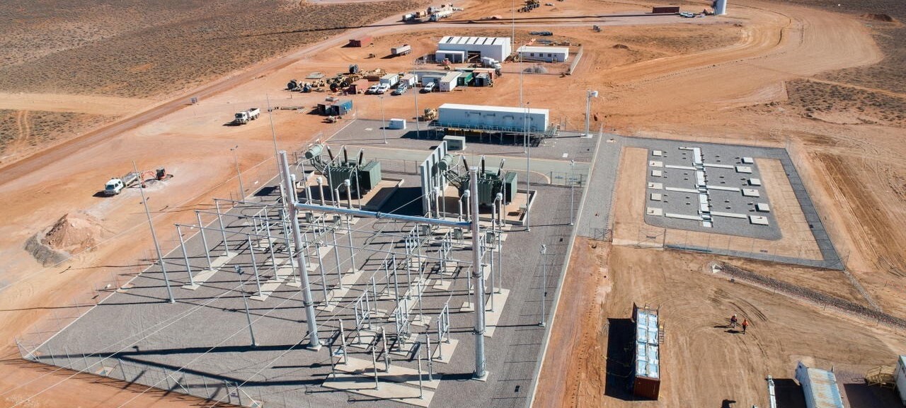
Power transformers play a crucial role in electrical systems by transferring electrical energy from one circuit to another. To keep them functioning safely and efficiently, they need to be regularly inspected and tested. This guide focuses on testing high voltage power transformers before they are put into use (commissioning) and as part of routine maintenance
Whether a transformer is new or has been in service for many years, testing helps identify any issues like insulation breakdown, oil leakage, or component failures. Fixing these problems early can prevent more serious issues, such as electrical failures or costly downtime.
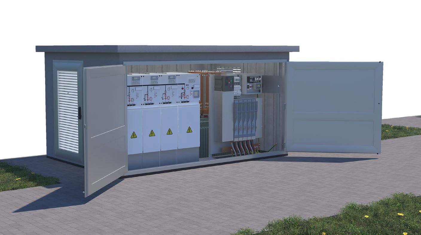
Types of Power Transformers Covered
If you’re working with power transformers in Australia, here are some key standards to be aware of:
- AS 2374 Parts 1 to 8 – These standards cover general requirements for power transformers.
- AS 2467-1981 – This standard outlines safety principles for working with high voltage equipment.
- AS 60076.1 – 2005 – This is the main standard for power transformers, covering testing, design, and construction.
- AS 1883-1992 – A guide for maintaining and supervising insulating oils used in transformers.
- AS 1767.1-1999– Specifications for unused mineral insulating oils.
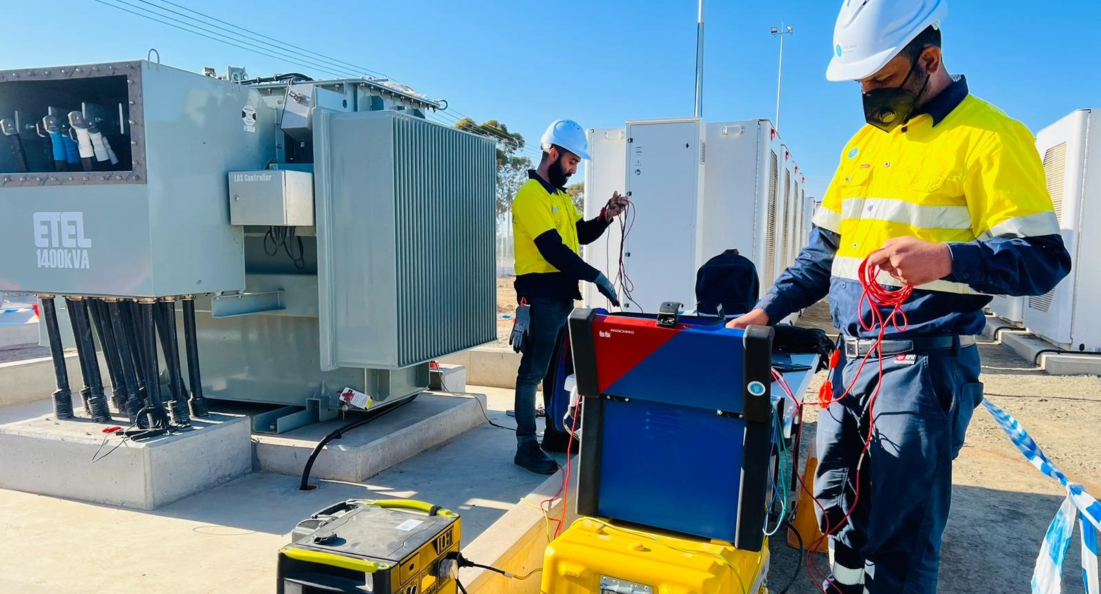
Safety First: Precautions for Testing Power Transformers
Safety is the most important aspect of power transformer testing. Testing should always be done with the transformer switched off and de-energized. Here are some key precautions:
- Avoid High Voltage Exposure: Ensure no one is near the transformer’s primary and secondary connections.
- Manage Fault Currents: Keep an eye on the possibility of high fault currents, which can be dangerous.
- Handle CT and VT Windings Carefully: Make sure the secondary windings of Current Transformers (CTs) and Voltage Transformers (VTs) are properly earthed (grounded). An open CT secondary can generate dangerously high voltages.
- Check Stored Energy in Windings: When testing winding resistance, be aware that there could be stored energy in the magnetic field.
- Work at Safe Heights: Transformers are large, so safety harnesses and fall protection might be needed.
- Avoid Chemical Hazards: Transformer oils can sometimes contain hazardous chemicals like Polychlorinated Biphenyls (PCBs). Handle with caution.
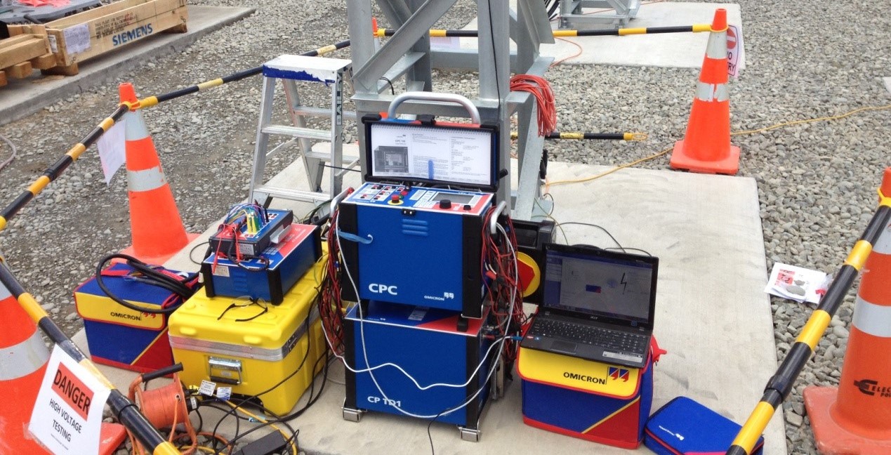
Step-by-Step Guide: Power Transformer Testing Procedure
Before you start testing, it’s important to complete a visual inspection. This ensures there are no obvious problems and sets a baseline for your test results.
1. Visual Inspection Checklist
- Check for Oil Leaks: Look for oil leaks on the transformer tank and around the pipework. Leaks can indicate internal issues.
- Inspect Paintwork and Rust: Check the transformer’s outer surface for rust or flaking paint, which could suggest exposure to moisture.
- Examine Bushings: Make sure bushings are clean and intact, and check their oil levels if they are oil-filled.
- Confirm Correct Labels: Check that all primary and secondary connections are correctly and clearly labelled.
- Look at Silica Gel Breathers: If the transformer has Silica Gel breathers, ensure they are not saturated. If more than 50% of the Silica Gel has turned color, it’s time to replace it.
- Inspect Gauges and Indicators: Check that gauges such as the Oil Temperature Indicator (OTI) and Winding Temperature Indicator (WTI) are functional.
Test Voltages
Australian standard AS2467-1981 provides a guide for test voltages
|
3 phase rating of primary insulation of equipment under test kV |
Test voltages recommended for insulation resistance (to earth and between phases) kV d.c. |
|
Up to 1 |
1 |
|
Above 1 to 3.6 |
2 |
|
Above 3.6 to 12 |
5 |
|
Above 12 |
10 |
As a rule of thumb for calculating these voltages use the following calculations:
For phase to phase voltages DCt = 0.8165 x Ep-p
For phase to ground voltages DCt = 1.4142 x Ep-n
DCt - the maximum insulation stress during normal ac operation
Ep-p – Maximum Phase to Phase voltage rating Um
Ep-n – Phase to ground rating derived from Um
2. Diagnostic Insulation Resistance Testing
- Spot Test: This test involves applying a voltage for a short period, usually 60 seconds, and recording the insulation resistance. It’s a quick way to see if the insulation is in acceptable condition.
- Polarization Index (PI): This test compares the insulation resistance at 10 minutes to the resistance at 1 minute. A PI value above 2.0 indicates good insulation. If it’s below 1, there could be serious problems.
How to Perform Insulation Tests:
1. Remove or isolate all neutral and earth connections.
2. Short the winding phases together for the test.
3. Short the CT secondary windings and connect to earth.
4. Short one side of all VT secondary windings.
5. Apply the insulation tester to each winding and take readings after 60 seconds.
3. Adjust for Temperature and Humidity
Insulation resistance can vary depending on the ambient temperature. For accurate results, it’s best to conduct tests at a standard temperature of around 20°C. If that’s not possible, use the following rule of thumb:
- Double the resistance for every 10°C below 20°C.
- Halve the resistance for every 10°C above 20°C.
For example, if the resistance at 40°C is 1 megohm, it would translate to 2 megohms at 30°C. Keep in mind that high humidity can also affect readings. If condensation forms on the insulation, it can lower resistance values, giving you a false sense of poor insulation quality.
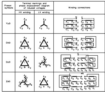
Vector group/phase relationship tests
Using a voltage source and a phase angle meter, check the relationship between primary
and secondary voltages to confirm the vector group of the transformer.
Connect an AC voltage source to one winding on the HV side of the transformer, and measure the phase angle difference between HV and LV. Phase displacement should follow the conventions outlined in the table below:
Complete final checklist
The following list details all of the checks that should be completed before a transformer is energised.
- Voltage Ratio Test
- Winding Resistance
- Insulation Resistance
- Current Transformers tested
- Voltage Transformers tested
Main Tank Buchholz relay
- Direction correct
- Low Oil Level Screw Removed
- Surge Vane settings
- Gas/Low Oil Alarms
- Low Oil/Surge Trips
- Buchholz bled
- No operation on pump start
- Diverter Switch Surge relay Alarm/Trip
- Qualitrol Trip
Oil
- Oil levels in main tank, oltc tank, bushings
- Oil level Low/High Alarms – main tank
- Oil level Low/High Alarms – tapchanger
- Oil Valves in service position
- Oil samples taken and tests results reviewed
- Oil Leaks
Oil temperature
- Thermal calibration
- Alarm
- Trip
- MDI reset
Winding temperature
- Thermal calibration
- Electrical calibration
- Alarm
- Trip
- MDI reset
Cooling Fans
- Operation – Manual and Automatic
- Direction
- Alarms
- Thermal overloads set
- Control switches left in service position
Cooling Pumps
- Operation – Manual and Automatic
- Direction
- Alarms
- Thermal overloads set
- Control switches left in service position
On Load Tap Changer
- Continuity between taps
- Local control (at tap changer mechanism)
- Remote control (at substation control panel)
- HMI control (at SCADA)
- Alarms at Protection Panel
- Raise/Lower correct direction
- Stop between taps, limit switches
- Out of step lockout
- Thermal overloads and timers set
- Control switches left in service position
General
- HV and Neutral connections correct
- DLA caps in place
- Earth connections correct
- Internal HV fuses in place for VT, auxiliary transformer
- Control Wiring terminals and links tightened
- Fuse and link carriers loaded correctly
- Operational Nameplate in place
- Mark up drawings
- On-load checks
Wrapping Up: Why Regular Transformer Testing Matters
Regular testing of power transformers is not just about compliance with standards—it’s about ensuring reliability and safety. A well-maintained transformer operates more efficiently, is less likely to fail, and costs less to repair over time. By following this guide, you can catch potential problems early and keep your transformers in optimal condition.
Always remember: transformer testing should only be carried out by trained and qualified personnel who understand the complexities of high-voltage equipment. And when in doubt, consult the manufacturer’s manuals or seek professional advice.
With the right approach and attention to safety, power transformer testing can be an effective way to protect both your equipment and the people working around it.