


Star connected Transformer:
Delta connected Transformer:
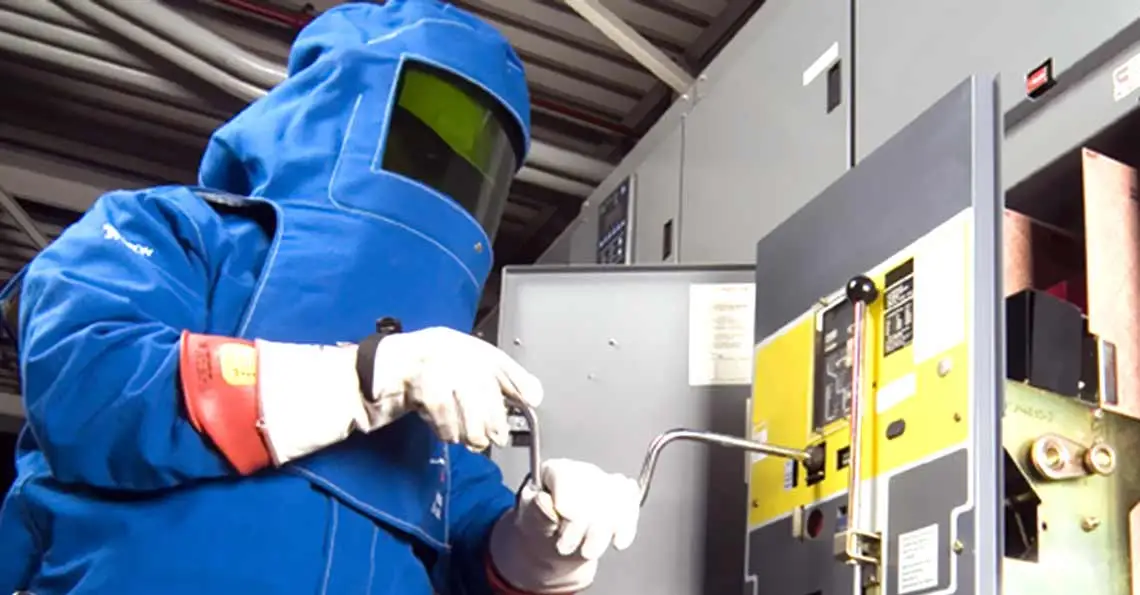
The importance and necessity of conducting this test cannot be overemphasised. Windings within the transformer are designed to operate on a certain amperage and voltage level which also needs to be fairly balanced with amongst all windings. Slight deviation between windings can be allowed; however, the allowable deviation depends on current carrying capacity of the winding.
Winding resistance is measured at ambient temperature first and then scaled at 75°C. Since most transformers are liquid cooled, it is unreasonable to measure temperature soon after de-energisation. A constant DC current of at least 10% of rated current is used to energise the windings until the change in voltage is either constant or very small.
After the test, a cooling off period of 3 to 8 hours is taken for the transformer oil to cool down to a stable temperature after which a reading is taken of the transformer oil. It is also interesting to note that the difference between the top and bottom portion of the oil tank may differ up to 5 degrees, which is why it is a good practice to take an average of three readings to determine a more accurate oil temperature.
Evaluation of the winding resistance test is commonly based on comparison with the original test data acquired at the time Factory Acceptance Testing (FAT) and the Site Acceptance Testing (SAT). However, in instances where FAT data is not available, inferences can be made by doing a phase-to-phase comparison of respective HV and LV sides. Normally, HV winding resistances are expected to be within 1% of each other whilst LV winding have a greater margin at 5%.
Upon completion of the test, it is recommended to demagnetise the core of the transformer to avoid excess residual flux from developing in the transformer core. Although not apparent right away, upon re-energisation, it can lead to huge inrush currents on primary side cause a false tripping on a differential scheme.